Seattle Subway
This project was inspired by the fine folks over at https://www.traintrackr.io/ They’ve done some really nice layouts of subways around the world. My sister got a christmas gift of the Boston one which inspired this project.
This project was done on a lark, but really exciting for me. I got to try some new tools, some new approaches, and some new ideas. It was a great amount of fun to get up and running.
What I like about building my own things is I get to make some choices of my own during design. I have chronic migraine, so bright flickery things (think PWM or matrixed LEDs) are a big no-no. I chose a LED driver chip with a high PWM rate (96kHz) and also tried to set up the constant current for the chip so that it wouldn’t need the PWM.
Short story, I failed and still need aggressive PWM due to a poor resistor choice. I also chose poorly for the power supply LED as that’s eye scorchingly bright. It was a bad math day.
I’ve also really been wanting to do a bare board design using an ESP32 module instead of a dev board. I’ve been thinking of building something that may require 100 boards. So I’ve been trying to figure out how to scale my production cost effectively without breaking the bank or myself trying to make them all.
Hardware
I used EasyEDA Pro from JLCPCB for the project. I also used their assembly service. Which continues to amaze me. I finished the design on a Sunday and the populated PCB’s made it to Seattle by Friday.
I start my part selection process by getting a rough feel for what I need. Some sort of ESP32, a LED driver, and a beefier LDO voltage regulator. I then search https://jlcpcb.com/parts/all-electronic-components to find candidates. I pay particular attention to the stock on hand, always prioritizing parts where they have a lot of stock so I’m not stuck waiting on stock or having to redesign.
The final choices:
- ESP32-S2-SOLO-N4R2: This has PSRAM built in, so one less thing for me to learn. It also supports USB natively so no need for another chip to do that. I wanted one with PSRAM because I knew the REST API I was going to be using returned a large JSON blob that needed to be manipulated.
- TLC59116 LED DRIVER (https://www.ti.com/lit/gpn/tlc59116): they had lots, it was constant current and a high frequency PWM for dimming
This is where my hardware design probably differs from a real production product. I paid extra to get a chip with a lot of onboard RAM so I could parse the JSON and turn it into a bit array on the device itself. Given how cheap google cloud functions are, and if I was feeling more ambitious, I would do that calculation in the cloud and use a cheaper part. That said, a huge part of my board cost was the additional $25 fee to upgrade to “Standard” quality which was required for the ESP32.
Schematics


PCB Routing
I hand routed this whole thing. One of the things I like about the ESP32 is how flexible it’s pins are. I2C can be set on pretty much every pin, so I had to iterate a few time as I fixed the routing. One thing I originally messed up was the placement of the esp32. This final location is NOT recommended by the ESP32 folks, but at least the antenna isn’t shadowed by the ground plane.

Bringing up the Board
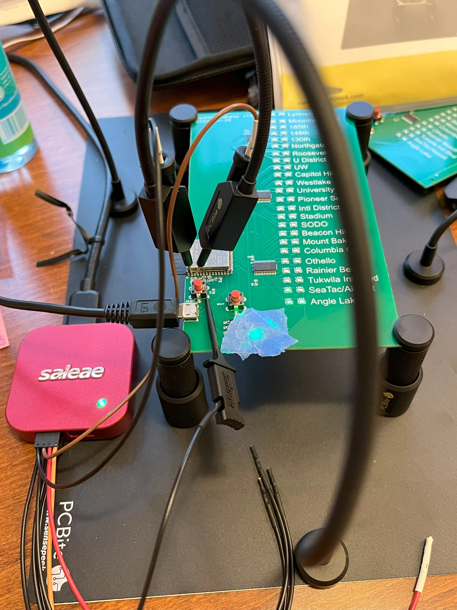
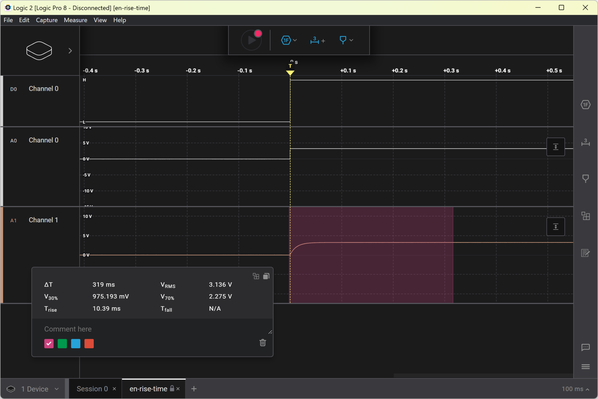
The first step for me was making sure I got the power on sequencing correct. The reference was pretty clear that you should use a little RC tank to make sure EN only goes after the appropriate amount of time. I busted out the Saleae Logic Pro 8 to confirm it was working right.

saleae setup to monitor power and pins

The goal was a few milliseconds. Built in measurement put it at 319ms. Win!
I2C
This was a little more difficult to get working correctly. I learned the hard way why the USB CDC (the built in USB on the ESP32) is not always the best idea. It ends up if the rtos crashes early during startup, you don’t get ANY output from USB. So no monitoring. No printf debugging. This was a few hours of my life I will never get back.
Thankfully I was able to configure ESP-IDF menuconfig to use a different UART for debug output. I setup the Saleae with a UART decoder and was very quickly able to see the problem.

Next up I wanted to check the rise time. I got to use my test points! First time I planned ahead enough :). I wasn’t sure if the 5MHz/50MSPS was high enough to spec out fast mode. It looks like 3.4MHz is needed to measure 300ns the long side of the spec and 47.5MHz is needed for the 20ns minimum rise time. So if I only cared about going too long I could have used the saleae. In any case, I have a Siglent SDS1104X-E so I used that.

This was a bummer. I was hoping to do fast mode, I used 10K pullup resistors instead of the weak 47K ones built into the ESP32. Alas, the spec for rise time (30% to 70%) must be 0.3us or less, I got 0.32. Probably good enough, but normal mode is working just great.

Here you can see crosstalk between SDA and SCL. Which is not a surprise at all given how I routed the board (long thin parallel traces).
LED Driver
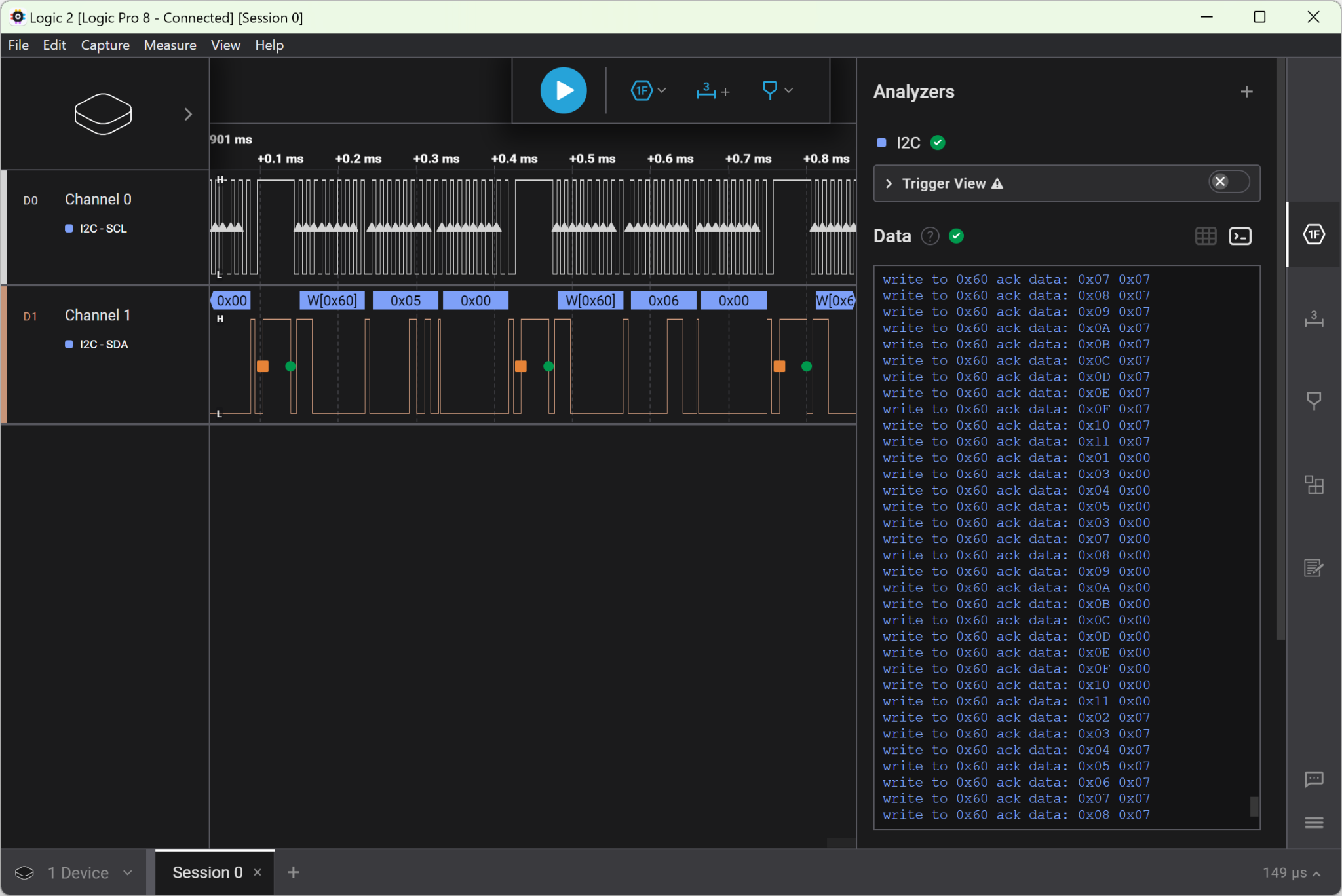
I’m using ESP-IDF directly, so I ended up cribbing some I2C sample code from Espressif and writing my own little driver. I used the saleae to snoop on the bus to make sure the code I was writing was doing what I expected over the wire. Worked like a charm.

saleae Logic 2 showing the I2C output
Python and JSON Parsing
The json returned from the One Bus Away API location API returns the location of everything in the Sound Transit fleet. It’s not very small. I used the https://github.com/espressif/json_parser to parse the results from https://api.pugetsound.onebusaway.org/api/where/vehicles-for-agency/40.json?key=GET_YOUR_OWN_KEY.
But practically starting with C code on a microcontroller is a recipe for pain. I did most of the authoring in python on my desktop and then converted that code manually over to what I needed in C.
Tools
I ended up using the following tools while working on this project.
Saleae Logic Pro 8 (https://www.saleae.com)
I got this because I really wanted to keep my scope off my desk if I can. It’s noisy, I often have a headache, and it takes up a bunch of space on my desk. I have some other logic analyzers, but their software isn’t as good and they don’t do any analog. If your budget can swing it, I highly recommend the Logic 8 Pro.
Siglent SDS1104X-E
My workhorse when I need a fast 8 bit scope. I can’t help but wonder if my 320ns timing for the I2C would have been lower with the 12 bits from the Saleae. I didn’t setup the Siglent very well so the signal was pretty quantized. These days I wouldn’t recommend this scope. I would look at a 12 bit scope like the newly released SDS800X series: https://siglentna.com/digital-oscilloscopes/sds800x-hd-digital-storage-oscilloscope/
PCBite
OK, this was a gamechanger for me. It really lowered my frustration level when having to probe the board. I wish I had gotten one sooner. I got the deluxe kit: https://sensepeek.com/pcbite-kit-with-2x-100mhz-and-4x-sp10-handsfree-probes.
EasyEDA Pro
It’s not Kicad. But it works really well with the JLCPCB Assembly service. Just really well integrated so it’s won me over for now.
Overall a very fun project. It wasn’t too bad from the frustration factor and I love having the ambient display of the trains in Seattle. I took the opportunity to grow my skills, build something I can display, and avoid using a soldering iron.
Conclusion
Overall a very fun project. It wasn’t too bad from the frustration factor and I love having the ambient display of the trains in Seattle. I took the opportunity to grow my skills, build something I can display, and avoid using a soldering iron.